Sector Model Export
The Sector Model Export feature exports a subset of a simulation model to a standalone DATA file that can be used as input for a new simulation. It supports boundary conditions, grid refinement, model padding, and optional direct integration with an OPM Flow simulation job.
To launch the wizard, right-click on a 3D View and select Export Sector Model.
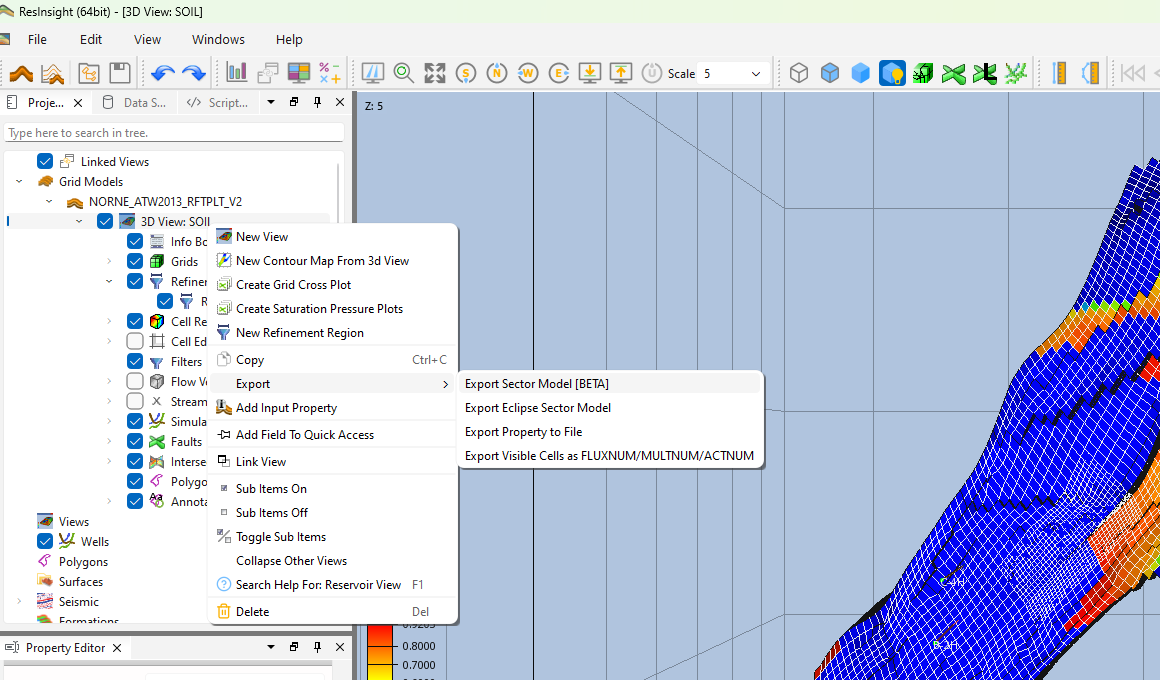
The export uses the source DATA file as a template: the grid and grid properties are cropped to the selected sector, and keywords referencing IJK ranges are rewritten so they remain valid in the sector coordinate system. This includes box-indexed keywords (EQUALS, MULTIPLY, BOX, COPY, ADD), aquifer keywords (AQUCON, AQUANCON, AQUNUM), non-neighbor connections (EDITNNC), faults, and well keywords (WELSPECS, COMPDAT, COMPSEGS) for the wells that intersect the sector.
The export is configured through a step-by-step wizard with the following pages.
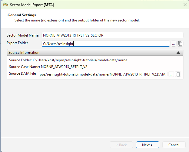
General Settings
Specify the name and output folder for the new sector model.
- Sector Model Name – The base name (without extension) for the exported DATA file.
- Export Folder – The folder where the exported files will be written. Must differ from the source case folder.
- Source Information – Shows the source case name and folder, along with:
- Source DATA File – The input DATA file used as the template for the export. Defaults to a DATA file located next to the grid file, with the grid file’s base name. A different DATA file can be selected.
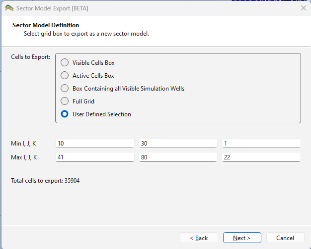
Sector Model Definition
Select which cells to include in the export.
- Cells to Export – Choose one of the following options:
- Visible Cells Box – IJK bounding box around currently visible cells (controlled by range and property filters in the view). This is the default.
- Active Cells Box – IJK bounding box around all active cells in the grid.
- Box Containing all Visible Simulation Wells – IJK bounding box surrounding the visible simulation wells, extended by a configurable number of cells.
- Well Padding – Number of extra cells to add around the wells (default: 2).
- Full Grid – The complete grid including inactive cells.
- User Defined Selection – Enter the IJK min/max ranges manually.
The dialog shows the Total cells to export to help assess the size of the sector model.
Refinement
The exported grid can optionally be refined by subdividing cells within one or more refinement regions.
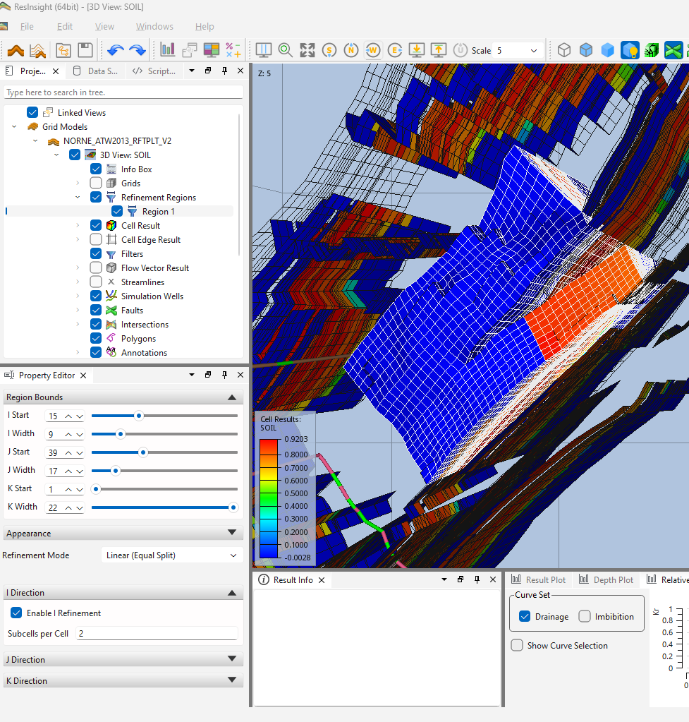
Refinement Regions
Refinement regions are created and managed in the 3D view, not in the wizard. To create one, right-click the 3D view and select New Refinement Region. The region appears in the Project Tree under the view and is shown as a colored wireframe box in the 3D view.
Each refinement region has the following properties:
- Name – Region name shown in the Project Tree and in the wizard.
- Show in 3D View – Toggles the wireframe preview of the region.
- Region Bounds – I Start/I Width, J Start/J Width and K Start/K Width sliders defining the IJK box to refine. A new region defaults to a centered box covering roughly a quarter of the grid extent in I and J, spanning the full K range.
- Preview Color – Color of the wireframe box.
- Refinement Mode – How the cells inside the region are subdivided:
- Linear (Equal Split) – Each cell is split into a fixed number of equal subcells, given by Subcells per Cell (range 2–100).
- Custom Widths – A comma-separated list of Fractional Widths defining the subdivision of each cell (e.g.
0.5, 0.5). - Logarithmic (Towards Center) – A given Total Cells count is distributed across the region with cell sizes decreasing logarithmically towards the region center.
Refinement can be enabled independently per direction with Enable I Refinement, Enable J Refinement and Enable K Refinement.
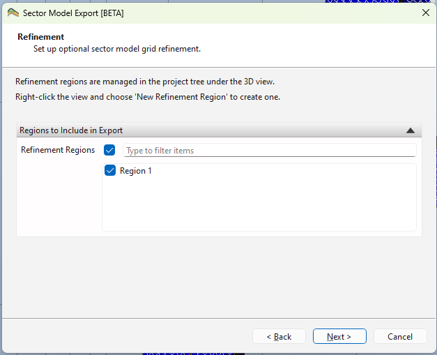
Refinement Wizard Page
The wizard page selects which regions to use in the export:
- Regions to Include in Export – Check the refinement regions to apply. Existing regions are preselected. Each selected region must lie entirely within the exported sector box.
Grid result values are not interpolated when refining; all sub-cells inherit the value of their parent cell. The MINPV value in the exported DATA file is scaled down automatically to match the refinement, so that refined sub-cells are not deactivated by the pore volume threshold.
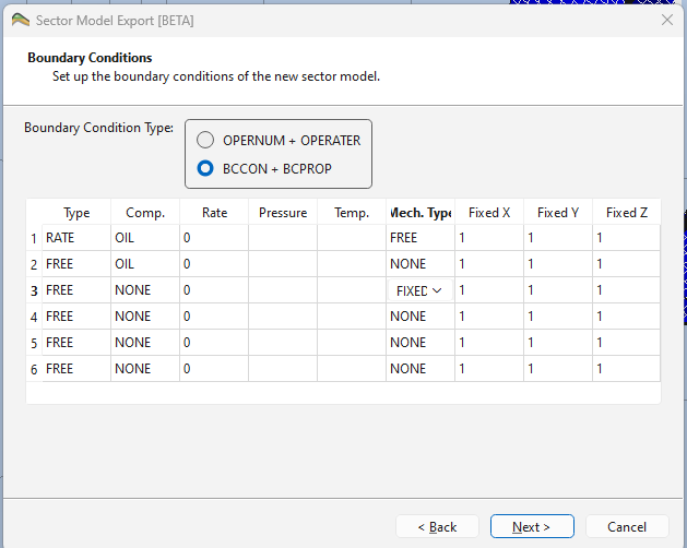
Boundary Conditions
Configure how boundary conditions are defined for the sector model faces.
- Boundary Condition Type – Select one of:
- OPERNUM + OPERATER – Uses OPERNUM and OPERATER keywords to define boundary conditions. A PORV Multiplier can be set to scale the pore volume at the sector model boundary (default: 1.0e6). This is the default.
- BCCON + BCPROP – Uses BCCON and BCPROP keywords. A table of BCPROP keywords is shown, with one row per BCCON region. The number of rows is determined automatically from the maximum BCCON value found in the grid (defaulting to 6 for the six faces).
Keyword Adjustments
Control which keywords from the source DATA file are excluded from the exported sector model.
- Keywords to Remove from Output – A list of keywords that will be stripped from the export. The default list contains:
ACTION,ACTIONX,ACTIONW,BOX,UDQ. Use the Reset to Default button to restore this list.
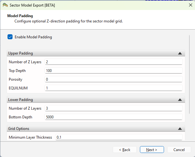
Model Padding
Optionally extend the sector model grid in the Z direction by adding inactive padding layers above and/or below the exported cells. This can be useful to ensure that the sector model has a complete pressure column.
- Enable Model Padding – Check to activate padding.
Upper Padding
- Number of Z Layers – Number of padding layers to add above the model.
- Top Depth – Depth of the top of the uppermost padding layer.
- Porosity – Porosity value assigned to the upper padding layers (range 0–1).
- EQUILNUM – EQUILNUM region number for the upper padding layers.
Lower Padding
- Number of Z Layers – Number of padding layers to add below the model.
- Bottom Depth – Depth of the bottom of the lowermost padding layer.
Grid Options
- Minimum Layer Thickness – Minimum thickness of each padding layer (default: 0.1).
- Fill Gaps in Z Direction – Fill any gaps between the model and the padding layers.
- Enforce Monotonic Z-Corners – Ensures that Z-corner values are monotonically increasing.
- Make Pillars Vertical – Forces the pillars of padding cells to be vertical.
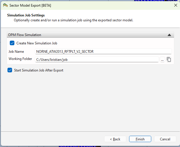
Simulation Job Settings
Optionally create an OPM Flow simulation job from the exported sector model, and/or immediately run it.
- Create New Simulation Job – Check to add a new OPM Flow job using the exported sector model DATA file as input.
- Job Name – Name of the new simulation job (defaults to the sector model name).
- Working Folder – Folder where the simulation job will store input and output files. Must differ from the export folder and the source case folder.
- Start Simulation Job After Export – When checked, all existing OPM Flow jobs that use the exported sector model file as input will be started automatically after the export completes.
See OPM Flow Integration for more details on working with simulation jobs.