Completions
The completions defined in ResInsight can be exported for use in new simulation runs. The commands Export Completion Data For Visible Wells and Export Completion Data For Selected Wells can be used to invoke the export. The commands are available by right clicking Well Paths in the Project Tree. The first command is available from the File->Import menu as well.
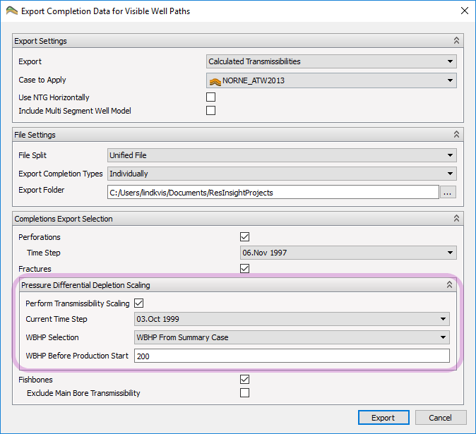
- Export Settings
- Calculated Transmissibilities – The transmissibilities calculated based on the case and completion data are exported directly
- Default Connection Factors and WPIMULT – The information about the connections for the simulator to be able to make the transmissibility calculation is exported for the COMPDAT/COMPDATL keywords. In addition, the same transmissibility calculation is performed by ResInsight, and the factor between the actual transmissibility for the connection and the simulator calculation is exported in the WPIMULT keyword.
- Case to Apply – Select which case to use for the export. Matrix transmissibilities will be read from this case.
- Use NTG Horizontally – Toggles whether NTG in I and J directions is included in the calculation
- Include Multi Segment Well Model – Toggles whether to also export the completions as Multi Segment Wells.
- File Settings
- File Split – Controls how ResInsight splits the export in different files
- Unified File – One file with all the completions.
- Split on Well – One file for each well
[Deprecated] Split on Well and Completion Type – One file for each well and completion type (Perforation Interval, Fishbone, …)
[Deprecated] Export Completion Types – Control how several completions of different type in the same cell are handledIndividually – Completions of each type are exported to separate sections in the file and not combined in any way.Combined – Connection factors from different completion types are added together producing one number for each cell.
- Export Folder – Folder for the exported COMPDAT file(s). The folder will be created when performing the export and the names of the exported file(s) will be auto generated.~~
- File Split – Controls how ResInsight splits the export in different files
- Completions Export Selection
- Perforations – Option to include or exclude perforation intervals in the export.
- Time step – Which timestep to export. This option is included since perforation intervals have a start time, and thus not all perforations need be present at all time steps.
- Fractures – Option to include or exclude fracture completions from the export.
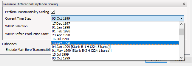
- Pressure Differential Depletion Scaling – Options to scale transmissibilities based on the well drawdown. This allows the simulation to more accurately model cases with high differential depletion.
- Fishbones – Option to include or exclude fishbone completions from the export. The direction reported in the COMPDAT/COMPDATL keywords is computed based on the orientation of the main bore cell the fishbone is connected to.
- Exclude Main Bore Transmissibility – If this options is checked on, only the transmissibilities for the fishbone laterals will be included in the export, and transmissibility along the main bore will not contribute.
- Perforations – Option to include or exclude perforation intervals in the export.
Transmissibility Calculations
The transmissibility calculation is performed for each direction, X, Y and Z, in an orthogonal coordinate system local to the cell.
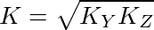
Taking the X direction as an example, we first calculate the relevant permeability K from the reservoir simulation properties PERMY (Ky) and PERMZ (Kz):
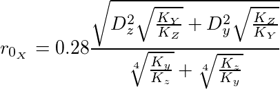
The Peacman radius (pressure equivalent radius) for the cell is then calculated, using permeabilities and cell sizes (Dy and Dz):
The x-component of the transmissibility vector is calculated, using the length of the perforation in the x direction (lx), the well radius (rw) and skin factor (S):
![]()
![]()
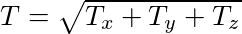
The y and z component of the transmissibility are calculated in the same manner, and the total transmissibility is then calculated as:
If the Export Calculated Transmissibilities is chosen in the export setting, this value is exported in the COMPDAT/COMPDATL keywords directly. If the Export Default Connection Factors and WPIMULT the transmissibility is chosen, the transmissibility is calculated as above, and in addition the transmissibility is calculated as the simulator would compute it using values other than transmissibility in the COMPDAT/COMPDATL keywords (perforation length, well radius etc). The ratio between these transmissibilities is then exported as the WPIMULT value.
For an example of COMPDAT files exported with calculated transmissibilities and with defaults and WPIMULT values, see export of Fishbones® completion data below.
Fracture Export
Pressure Differential Depletion Scaling
For cases with high differential depletion, it is possible to scale the transmissibilities from the grid cells into the well (via the fracture) by the well drawdown. This enables the simulation to take into account that the flow will take different paths into the well as the pressure differential between the surrounding grid cells increases. If enabled, a time step for the grid pressures have to be selected. The list of time steps will also show the time step in which the wells first show a Well Bore Hole Pressure (WBHP) larger than zero in the Summary Case information.
Having chosen a time step for differential depletion scaling a source for the well pressures can be chosen. If WBHP From Summary Case is picked, the WBHP value in the summary case for the chosen time step is used. However, if the chosen time step precedes the production start of a well, the value set in WBHP Before Production Start is used.
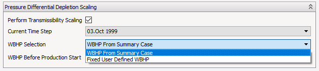
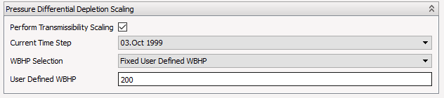
If, however, a Fixed User Defined WBHP is chosen, the provided WBHP value is used for all wells.
Fracture Report Header
At the top of the exported transmissibilities for fractures, a fracture report summary is displayed. This section displays the different properties for the fractures used to compute the transmissibility values.
Description of Derived Data
One of the tables displays derived data, see the example here:
- Tr – Accumulated computed transmissibilies for all reservoir cells intersected by the fracture
- #con – Number of reservoir cells intersected by the fracture
- Fcd – Area weighted fracture conductivity divided by area weighted matrix transmissibility (Kf/Km)
- Area – Area of reservoir cells(both active and inactive) intersected by the fracture
- KfWf – Multiplication of Kf by Wf (Kf * Wf)
- Kf – Area weighted average of permeability of fracture cells intersecting reservoir grid cells (using Area defined above)
- Wf – Area weighted average of width of fracture cells intersecting reservoir grid cells (using Area defined above)
- Xf – Half-length, defined as fracture area divided by half-height (Area/(H/2))
- H – Longest continuous distance with fracture cells open for flow along a fracture grid column
- Km – Area weighted average of matrix transmissibility (using Area defined above)
Differential Depletion Fracture Output
In addition to scaling the transmissibilities in the fracture output, using pressure differential depletion scaling will also provide a table with information regarding the scaling performed for each well. This table will show the well name, fracture name and the source of the Well Bore Hole Pressure (WBHP From Summary Case or Fixed User Defined WBHP). For WBHP From Summary Case the User WBHP column will describe the well pressure used for all time steps before the production starts according to the summary case information and the Actual WBHP will describe the well pressure used in the scaling, which will be different from the User WBHP if the scaling is performed for a time step following the well productions start. Finally the columns Min Pressure Drop and Max Pressure Drop describes the minimum and maximum well drawdown for this particular fracture.
Export of Fishbone Completion Data
The transmissibility calculation for the fishbones is done following the above description except that when calculating the transmissibility for the laterals, the full cell volume is split among the laterals for calculation of the transmissibility. This is done by finding the direction of the main bore, and then dividing the cell size in this direction by the number of laterals in the cell when calculating the Peaceman radius.
An example of the exported COMPDAT file is shown below. The calculated transmissibility contribution to the cell connection factor from each lateral or main bore part is included as a comment.
For export with WPIMULT factors, the main bore diameter and direction are given in the export for cells which have both main bore and lateral contributions, while diameter and main direction of the first lateral is used for cells with no main bore contribution. Other parameters exported as part of COMPDAT are set to default.
The WPIMULT parameters are calculated, as for the perforation intervals, by ResInsight calculating both the transmissibility of the completion as described above, and in addition calculating the transmissibility based on the information exported in the COMPDAT keyword. The ratio between these two numbers is then exported as the WPIMUT keyword.
Completions for LGR (WELSPECL and COMPDATL)
Completion data for LGR grids are exported to a separate file having the same name as the main grid completions file postfixed by “_LGR”. Instead of using the WELSPECS and COMPDAT keywords, the WELSPECL and COMPDATL keywords are used. Those tables are similar to the WELSPECS and COMPDAT tables, except from including the columns LGR and LgrName, respectively. The extra columns contains the name of the LGR grid.
LGR for completions (Temporary LGRs)
The previous section describes the export of COMPDATL for completions intersecting existing LGRs, loaded from file. This section will describe how to have ResInsight create temporary LGRs around completions, and then export COMPDATL for those LGRs. To accomplish this, do the following:
- Create LGRs for completions on selected well paths. See Completions LGR
- Export completions the usual way. See Completion Export
Info
In addition to the completion data, the geometrical definition of all temporary LGRs is also exported into “*.dat” files.
Multi Segment Well Model
It is possible to export all the completions to a text file containing the reservoir simulation input data keywords needed to represent the completions as a Multi Segment Well. This is done by checking the Include Multi Segment Well Model. All completions are supported and are exported in somewhat different ways.
Exported MSW Data
In the output file there are data for three simulator keywords specified.
WELSEGS
WELSEGS defines multi-segment wells. The list of entries contains information on the main stem, the ICDs at the fishbone subs and the fishbone laterals. A comment above each entry details which element (main bore / ICD / lateral) the entry is for. Example:
The first WELSEGS entry contains information about the well:
- Name - Name of well
- Dep 1 - TVD of start MD point, as given by the user in the Fishbones Start MD field.
- Tlen 1 - Point given by the user in the Fishbones Start MD field.
- Len&Dep - incremental or absolute, as specified by the user in the Fishbones property editor.
- PresDrop - specifies what is included in the pressure drop calculation, hydrostatic, friction or acceleration. Specified by user in the Fishbones property editor.
The following WELSEGS entries contains information about each segment:
- First Seg, Last Seg – Values are being exported pr segment, so both first and last segment number is the number of the segment being exported.
- Branch Num – Branch number for segment being exported.
- Outlet Seg – The segment the exported segment is connected to. For the main bore segments, this is the segment before them, for ICDs the segment number being exported and for fishbone laterals the segment on the main broe where the laterals are connected.
- Length – Length of segment (if incremental Len&Dep above) or length of segments including this along well (if absolute Len&Dep above). For ICDs length is set to 0.1.
- Depth Change – Depth of segment, incremental or absolute as for Length. For ICDs depth is set to 0.
- Diam – Diameter of segment. For main bore and ICD entries, the liner inner diameter for the Fishbones collection is used. For laterals, an effective diameter is calculated so that the diameter exported is the diameter which, assuming a circle, would give the same area as the area between the hole diameter and the tubing diameter.
- Rough – The roughness factor as entered by the user. Notice that a different value can be specified for the main bore and the laterals, as described above.
COMPSEGS
An example of the COMPSEGS keyword as exported is shown below.
The first COMPSEGS entry is a line with the well path name. Each following entry is for the segments in the well, and containing the following field:
- I, J and K – The cell index
- Branch no – Branch number for the segment
- Start Length, End Length – Start and end length along the well for the relevant segment.
WSEGVALV
An example of the WSEGVALV keyword as exported is shown below.
The parameters exported in the WEGVALV keyword are
- Well Name – The name of the well.
- Seg No – Segment number along the well.
- Cv – The ICD Flow Coefficient, as entered by the user.
- Ac – the total ICD area per sub, calculated as the area per ICD (given by the orifice radius) multiplied with the number of icd per Sub.
Export of Fractures and Perforations as Multi-Segment Wells
Fractures and Perforations may also be exported as Multi-Segment Wells. In the case of Fractures, ResInsight will create one segment for the entire fracture, with a number of COMPSEGS-entries corresponding to the cells intersecting the fracture. In this case, the Diam and Rough parameters are not used for anything and the length of the fracture segment is nominal. An example of a Fracture entry is shown below.
The entries for Perforations are simpler. No additional branches are created as the perforation intervals are all on the main bore and all perforated cells are listed as COMPSEG entries very similar to normal COMPDAT export of perforation intervals.