Seismic Sections
Creating a Seismic Section
Import of data is described in Seismic Data
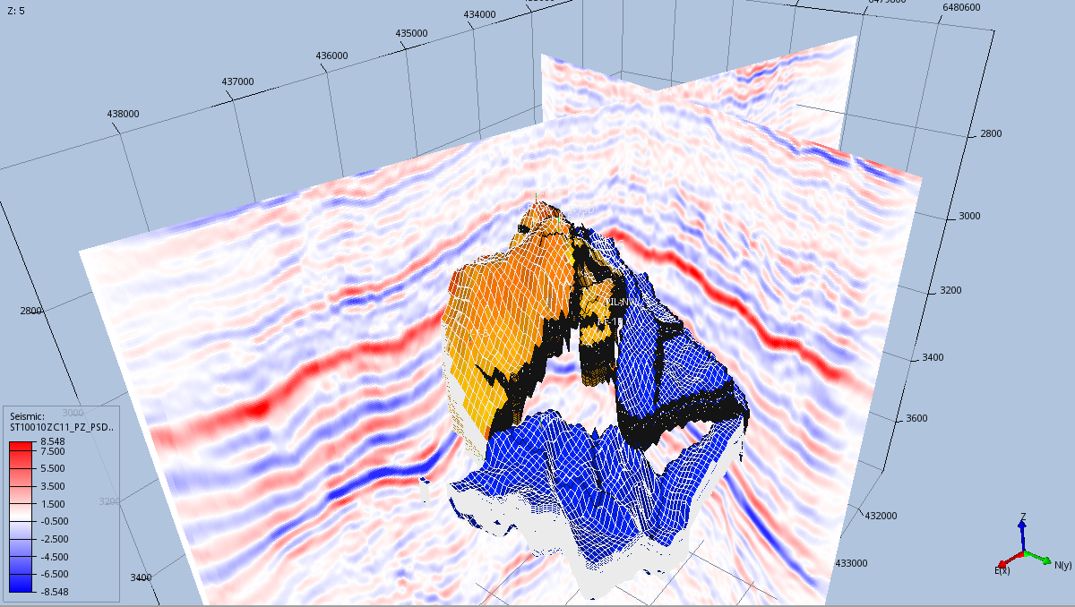
Seismic Sections are cross sections that cut a grid model in various ways to display seismic data. A Seismic Section is created by right-clicking the Seismic Section item in Project Tree
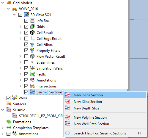
The following types of Seismic Sections are available:
- Inline Section: A seismic line within a 3D survey parallel to the direction in which the data were acquired.
- Xline Section: A seismic line within a 3D survey perpendicular to the direction in which the data were acquired.
- Depth Slice: Horizontal slice through the volume data of a 3D survey at a specific depth.
- Polyline Section: Seismic section following a user defined polyline on top a grid model for displaying volume data of a 3D survey, c.f. Polyline Intersection for specification of polyline.
- Well Path Section: Seismic section following a specific well path through the volume data of a 3D survey.
Property Editor
The Property Editor of a Seismic Section is shown below.
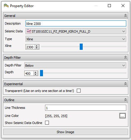
The properties are grouped as follows:
- General: Enables the user to provide a description, select seismic data, type and position of a Seismic Section.
- Depth Filter: Enables filtering of a Seismic Section by setting Depth Filter properties:
- None: no depth filtering
- Above: show above the specified Depth
- Below: show below the specified Depth
- Between: show between the specified Upper Depth and the specified Lower Depth
- Outline: Specifying line thickness, line color, and display of seismic data outline.
- Show Image: Displays the Seismic Section in a separate 2D view.